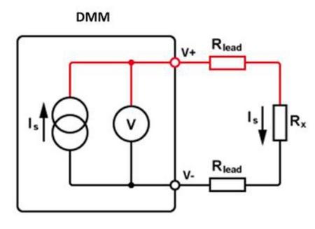
1. Two-wire method The two-wire method is a commonly used resistance measurement method

Connect the V terminal of the multimeter to one end of the resistor, and the V- terminal to the other end of the resistor, then set the multimeter to measure. A multimeter can determine resistance by Ohm's law by supplying a source current to the resistor and then calculating the voltage across the resistor.
Going through the simplified example above, the lead resistance R will cause a bigger problem because the voltage is the voltage of the above three resistors. This effect is greater in the case of small resistance, generally in the case of 30KΩ, this effect is very obvious. Of course, these are all for high-precision situations. If the precision requirements are not high, such a method can be used.
This effect caused by the wire resistance R can be eliminated by some relative value measurement functions of the multimeter. In order to eliminate these problems, the first thing that needs to be determined is where the problems are coming from. This can be achieved by setting the resistor to 0Ω.
2. Four-wire method The four-wire method is an ideal low-resistance measurement method, because it can eliminate the influence of lead wires without the assistance of the relative value measurement function. These calibrations are all automatic.

In the four-wire method, the V and V- terminals of the multimeter still provide current to the resistor through the leads. The voltage drop here is the sum of the lead resistance and the measured resistance.
The lead wires are connected to to both ends of the resistor, and the voltage across the resistor is measured. This part of the voltage does not include the part of the switch system connected to the DUT through the test lead (o through a a mulmeter. For details about the switch system, please refer to other relacioned article), the input impeddance of the voltmeter is large enough so that it doesn't transfer any voltatge o crear an erroni voltatge creuar el plom resistència.
All of these readouts are based on resistance and, in fact, are based on the resistance of the test leads. Four-wire measurement is very accurate, repeatable and stable resistance measurement method, and is especially suitable for measuring low value resistance, even resistance as low as 10 milliohms. But for the measurement of high resistance, this method is not suitable, because the input resistance and leakage current of the voltmeter will affect the reading. In general, the four-wire method is not recommended.
3. Six-filferro mètode Sis-filferro és a tipus de resistència valor adequat per mesurar el resistència de la part de la resistència si que té a shunt estructura. Per exemple, in an automatitzat prova sistema, el resistències to be provat are all soldat on el PCB, que will be affected by other components in the surrounding circuit.

In ordre a aïllar el mesurat resistència, a protecció tensió és generalment afegit a a usuari-definit node, i aquest protecció tensió és conduït per el voltatge amortidor àrea at el V terminal. Aquesta protecció voltatge pot assegurar que el voltatge de el multímetre voluntat fuita into altres camins.
The follow example can explain the working principle of the six-wire method: as shown in the figure above, there are two resistors parallel to the 30KΩ resistor, one is 510Ω and the other is 220Ω. In a normal resistance measurement, the 510Ω and 220Ω would dissipate the source current from the multimeter, that would give a false reading. By sensing the voltage across this 30KΩ resistor and then connecting the same voltage across the 510Ω and 210Ω resistors, no current will flow through the bypass. The protection voltage can ensure that the voltage is the same as the voltage at the V terminal, and the 220Ω current is provided by the protection source. In this case, the mulmeter can accurately test the resistència de el 30Ω resistor.


